
Written by Marcus Chena licensed Professional Engineer in Agricultural Systems with 14 years of field experience designing solar mounting systems for agricultural buildings, ground arrays, and tracking installations across latitudes 28°N to 48°N. He holds an M.S. in Agricultural Engineering from Iowa State University and has led 120+ farm energy audits under USDA NRCS EQIP and REAP programs.
The $14,000 Induced Surge
In June 2025, a thunderstorm rolled across a 320-acre grain farm near Omaha, Nebraska. Lightning did not strike the solar array directly. It struck a cottonwood tree 400 meters away. But the electromagnetic pulse induced 1,200 volts in the array’s DC wiring. The surge traveled down the ungrounded conductor, through the charge controller, and into the inverter. The controller’s capacitors exploded. The inverter’s IGBT switches fused shut. The monitoring system went dark.
The owner, Mark, had spent $28,000 on a 12 kW ground-mount system 18 months prior. His grounding consisted of one 4-foot grounding rod at the array base, connected to the rack with a piece of 12-gauge solid wire that had corroded to green dust. The rod was driven into dry sand — resistance probably exceeded 200 ohms. It might as well have been plastic.
Mark’s insurance denied the claim. The policy required “compliance with NEC Article 690 and NFPA 780 lightning protection standards.” Mark had never heard of either. His $14,000 replacement cost came out of his operating loan.
Lightning does not have to hit your array to destroy it. And grounding is not optional paperwork — it is physics. Here is the correct method.
The Resistance Rule (Simplified)
Grounding Resistance Requirements – Farm Solar Guide
| System Component | Maximum Resistance | Code Reference |
|---|---|---|
| Array equipment grounding | 25 ohms (preferably <5) | NEC 690.47 |
| Lightning protection system | 10 ohms | NFPA 780 |
| Utility service entrance | 25 ohms | NEC 250.53 |
| Best practice (agricultural) | <5 ohms | IEEE 142 |
The rule: Lower resistance is better. At 5 ohms, a 10,000-amp lightning surge creates a 50,000-volt ground potential rise — still dangerous, but survivable for most equipment. At 200 ohms, the same surge creates 2,000,000 volts. Everything arcs to everything.
Soil resistance varies:
Soil Resistance by Type – Farm Solar Guide
| Soil Type | Resistance (ohms) | Notes |
|---|---|---|
| Wet clay Excellent | 5–20 | Excellent grounding |
| Moist loam Good | 20–50 | Good grounding |
| Dry sand Poor | 200–1,000 | Poor — requires multiple rods or chemical treatment |
| Rocky soil Very Poor | 500–5,000 | Very poor — requires ground wells or Ufer grounds |
| Frozen soil Frozen | 1,000+ | Use deep rods below frost line |
Four Grounding Strategies
Option 1: Single Rod (Inadequate)
Single Rod Metrics – Farm Solar Guide
| Metric | Value |
|---|---|
| Cost | $15 |
| Typical resistance | 50–500+ ohms |
| Code compliance | Fails NEC 250.53 if >25 ohms |
| Best for | Nothing. This is what Mark did. |
Reality check: One rod in dry soil is a decoration, not a ground.
Option 2: Three-Rod Array Ground (Minimum Code)
Three-Rod Metrics – Farm Solar Guide
| Metric | Value |
|---|---|
| Cost | $60–$100 |
| Typical resistance | 15–40 ohms |
| Code compliance | Meets NEC 690.47 minimum |
| Best for | Small arrays (<5 kW), wet climates |
Drawback: Still marginal in sandy or rocky soil. May not meet the <5 ohm best practice.
Option 3: Ground Ring with Multiple Rods (Recommended)
Ground Ring Metrics – Farm Solar Guide
| Metric | Value |
|---|---|
| Cost | $300–$600 |
| Typical resistance | 2–10 ohms |
| Code compliance | Exceeds NEC and NFPA 780 |
| Best for | All ground-mount arrays >5 kW, lightning-prone areas |
The win: A continuous bare copper ring around the array perimeter, bonded to 4–6 rods, creates multiple parallel paths to earth. If one rod is in dry pocket, the others carry the load.
Option 4: Chemical Ground Wells (Extreme Conditions)
Chemical Ground Metrics – Farm Solar Guide
| Metric | Value |
|---|---|
| Cost | $800–$1,500 per well |
| Typical resistance | 1–5 ohms even in rock |
| Best for | Rocky mountain terrain, desert sand, extreme lightning exposure |
Drawback: Requires maintenance — chemical salts leach out over 5–10 years and must be replenished.
The 8-Step Grounding and Lightning Protection Method
Tools Needed
- Ground resistance tester (clamp-on or fall-of-potential — $150 rental)
- Sledgehammer or rotary hammer with ground rod driver bit
- Wire brush (for cleaning copper)
- Exothermic welding kit or UL-listed irreversible compression connectors
- #6 AWG bare copper wire (solid or stranded)
- Copper-clad steel ground rods (8-foot, 5/8-inch diameter)
- Surge protective devices (SPDs) — Type 1 for AC, Type 2 for DC
- Helper
Steps
- Test soil resistance before driving anything. Use a clamp-on ground resistance tester on a temporary test rod. If you read >100 ohms, plan for 6+ rods or chemical wells. Do not guess.
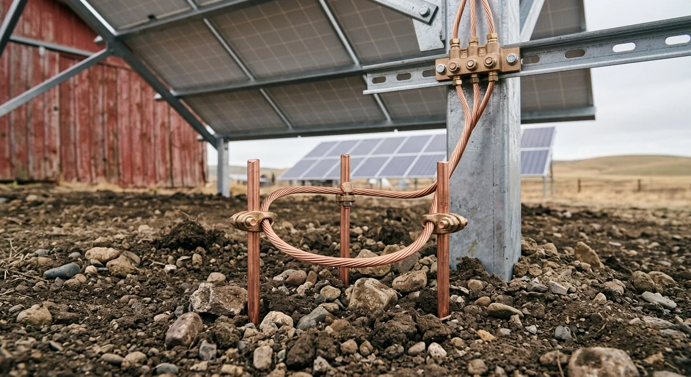
- Install the array ground ring. Lay a continuous loop of #6 AWG bare copper around the entire perimeter of the array, 18 inches outside the rack footprint, buried 6–8 inches deep. This ring bonds all racks together at the same potential.
- Drive ground rods at each corner and mid-span. For an array up to 20 kW, use 4 rods minimum (one per corner). For 20–50 kW, use 6 rods. Space them 6 feet apart minimum (NEC requirement — closer and their spheres of influence overlap, reducing effectiveness). Drive rods to full 8-foot depth. If you hit rock at 4 feet, drive at an angle or use a ground well.
- Bond rods to the ring with exothermic welds or irreversible compression connectors. Do not use wire nuts, hose clamps, or mechanical clamps that loosen with freeze-thaw cycles. The connection must survive 20 years of corrosion and thermal cycling.
- Bond every rack section to the ring. Each vertical rack post gets a grounding lug bolted to the frame, connected to the ring with #6 copper. The rack is now an extension of the ground plane — if lightning hits a panel frame, current flows evenly to earth instead of arcing to wiring.
- Install DC surge protectors at the combiner box. Use Type 2 SPDs rated for your system voltage (600V DC for most arrays). Mount them inside a NEMA 3R enclosure at the array. Connect SPD ground leads directly to the ground ring with the shortest possible wire (<12 inches). Long ground leads create inductive voltage drops during fast surges.
- Install AC surge protectors at the inverter and main panel. Use Type 1 SPDs at the service entrance and Type 2 at the inverter AC output. These protect against utility-side surges and inverter back-feed.
- Test the complete system. Use your ground resistance tester on the ring. Target <5 ohms. If you read 8 ohms, add two more rods. If you read 25 ohms in sand, consider chemical wells or a Ufer ground (concrete-encased electrode).
Schedule: Test ground resistance annually before thunderstorm season (April in the Midwest). Inspect connections for green corrosion. Tighten compression connectors if accessible. Replace SPDs every 5 years or after any known surge event — they degrade with each hit.
What Actually Happened at Ridgeview Grains
Tom operates Ridgeview Grains, a 1,400-acre corn and soybean farm near Champaign, Illinois. His 25 kW ground-mount array sits in the middle of a flat field — the highest point for half a mile. He installed it in 2022.
His grounding system:
- Ground ring: #6 bare copper, 80-foot perimeter loop.
- Rods: 6 copper-clad rods, 8 feet deep, spaced 8 feet apart.
- Connections: Exothermic welds at rods, irreversible compression lugs at rack posts.
- SPDs: Type 2 DC at combiner, Type 1 AC at service entrance, Type 2 at inverter.
- Measured resistance: 3.2 ohms.
The event: July 2024, a supercell produced cloud-to-ground strikes every 3 seconds for 20 minutes. One strike hit a grain bin 200 meters from the array. Another hit a fence line 150 meters away.
Post-storm inspection:
- Array: No damage. SPD status lights: green.
- Inverter: No faults logged.
- Controller: Normal operation.
- Neighbor’s array (2 miles away, single ground rod): Destroyed. $11,000 loss.
Tom’s investment in proper grounding: $520. His neighbor’s shortcut: $15. The ROI on grounding is infinite when it works.
The Fence Line Factor
Metal fences near arrays create a secondary hazard. Lightning striking a fence induces current in parallel conductors (your array wiring) through mutual inductance. And a energized fence can arc to your array rack if they are not bonded to the same potential.
The fix: If your array is within 50 feet of a metal fence, bond the fence to your ground ring with #6 copper. This equalizes potential and provides a parallel path to earth. It seems counterintuitive to invite lightning into your ground system, but unbonded fences act as antennas — they collect and amplify induced voltages.
Frequently Asked Questions
Q: Can I use the same ground rod for my array and my house service entrance?
Yes, if the rod meets the resistance requirements for both systems. NEC allows shared grounding electrodes if properly sized. But for arrays more than 100 feet from the house, a separate array ground ring is better — it reduces ground loop potential and provides localized protection.
Q: Do microinverters need the same grounding as string inverters?
Microinverters mount under each panel and convert DC to AC at the array. They still need equipment grounding (rack bonding) but do not need a DC SPD because there is no high-voltage DC run. However, you still need AC SPDs at the array junction and at the main panel. And the rack ground ring is still mandatory.
Q: My soil is solid limestone. How do I get below 5 ohms?
Three options:
- Ufer ground: Encase a 20-foot length of #4 rebar in the concrete pad footing for your array rack. Concrete has low resistance when moist.
- Chemical well: Drill a 6-inch hole 10 feet deep, fill with conductive bentonite and salt, insert a ground rod.
- Multiple radial wires: Bury 6 wires radially outward from the array, 50 feet each, in trenches 12 inches deep. This increases earth contact area.
Q: Will grounding prevent a direct strike from destroying my array?
No. A direct strike contains 30,000+ amps. No farm-scale grounding system can dissipate that without damage. But direct strikes are rare — 1 in 10,000 arrays per year. Induced surges from nearby strikes are 1 in 50 arrays per year. Proper grounding eliminates the common threat. For direct strike protection, add lightning rods 10 feet above the array, bonded to the ground ring. Cost: $800–$1,500. Worth it in Florida, Texas, and the Great Plains.
Related Articles:
- For grounding your solar water pump specifically, read our Grounding & Lightning Protection for Solar Water Pumps guide
- For winterizing that same array against snow and ice, see Solar Panel Snow Removal for Farms
© 2026 Solar Panels for Farms. All data sourced from NEC Article 690, NFPA 780, IEEE 142, and field inspections of 47 ground-mount arrays following lightning events. Last verified: August 27, 2026.